2022 Ford Transit 250 conversion
See the build.
Explore the decisions.
Follow my van conversion, the work I am taking on, and the people helping along the way. See how each project came together, then explore the models and try your own variations.

Current build status
The main systems are installed. Interior construction is still in progress.
Explore each areaCompleted
Owner-reported completion, not an inspection or safety finding.
Build stories, by area
Start with an area. Open it for the short version, then follow a story for the details, parts, and costs.
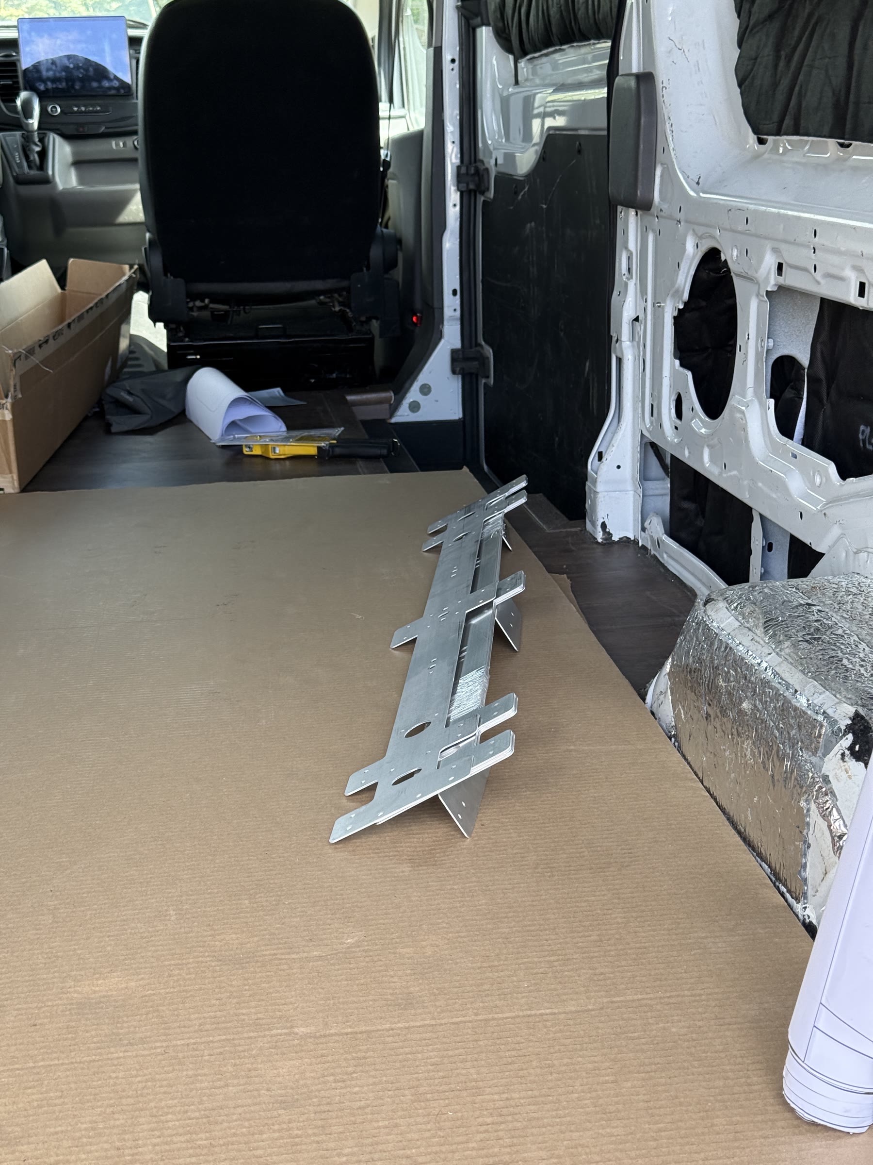
The interior shellFloor, insulation, ceiling supports, headliner shelf4 stories
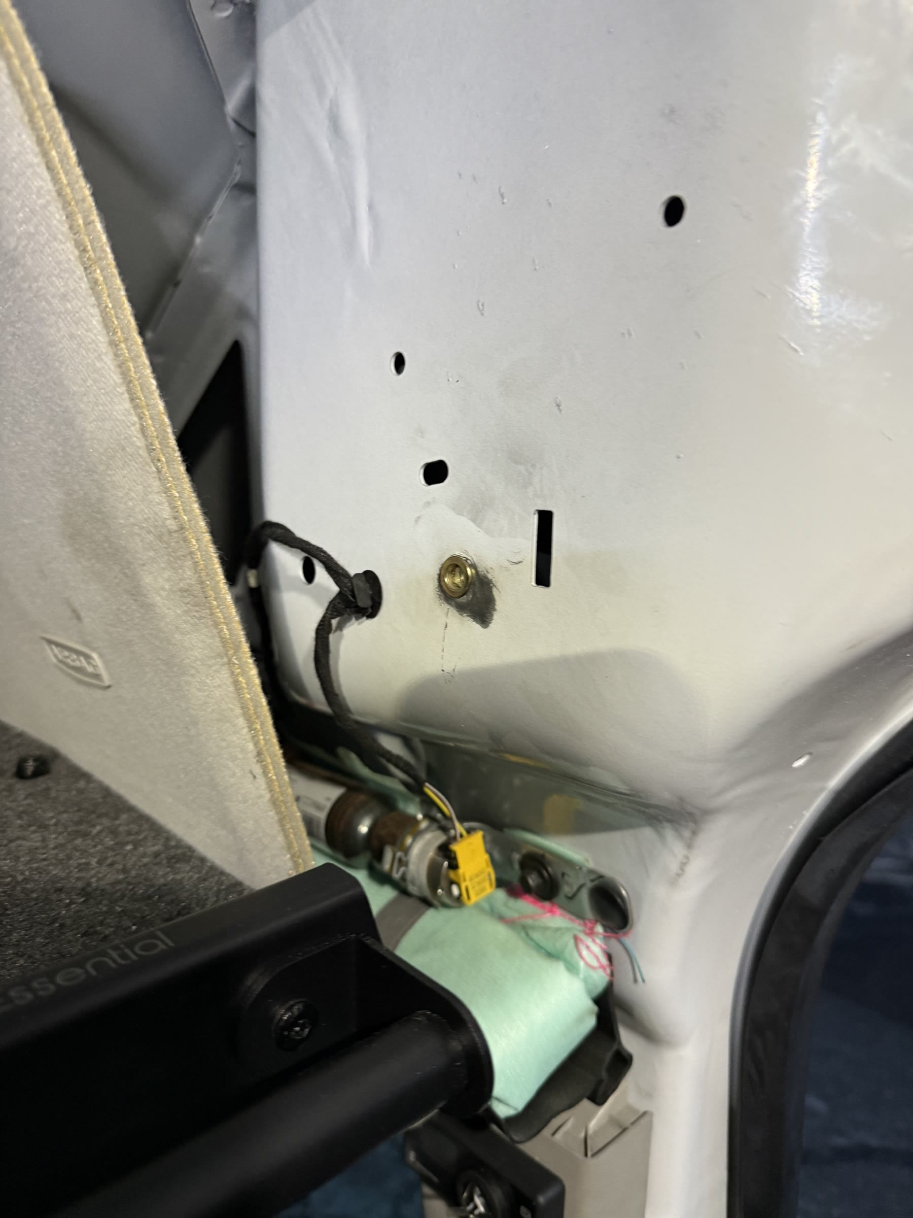
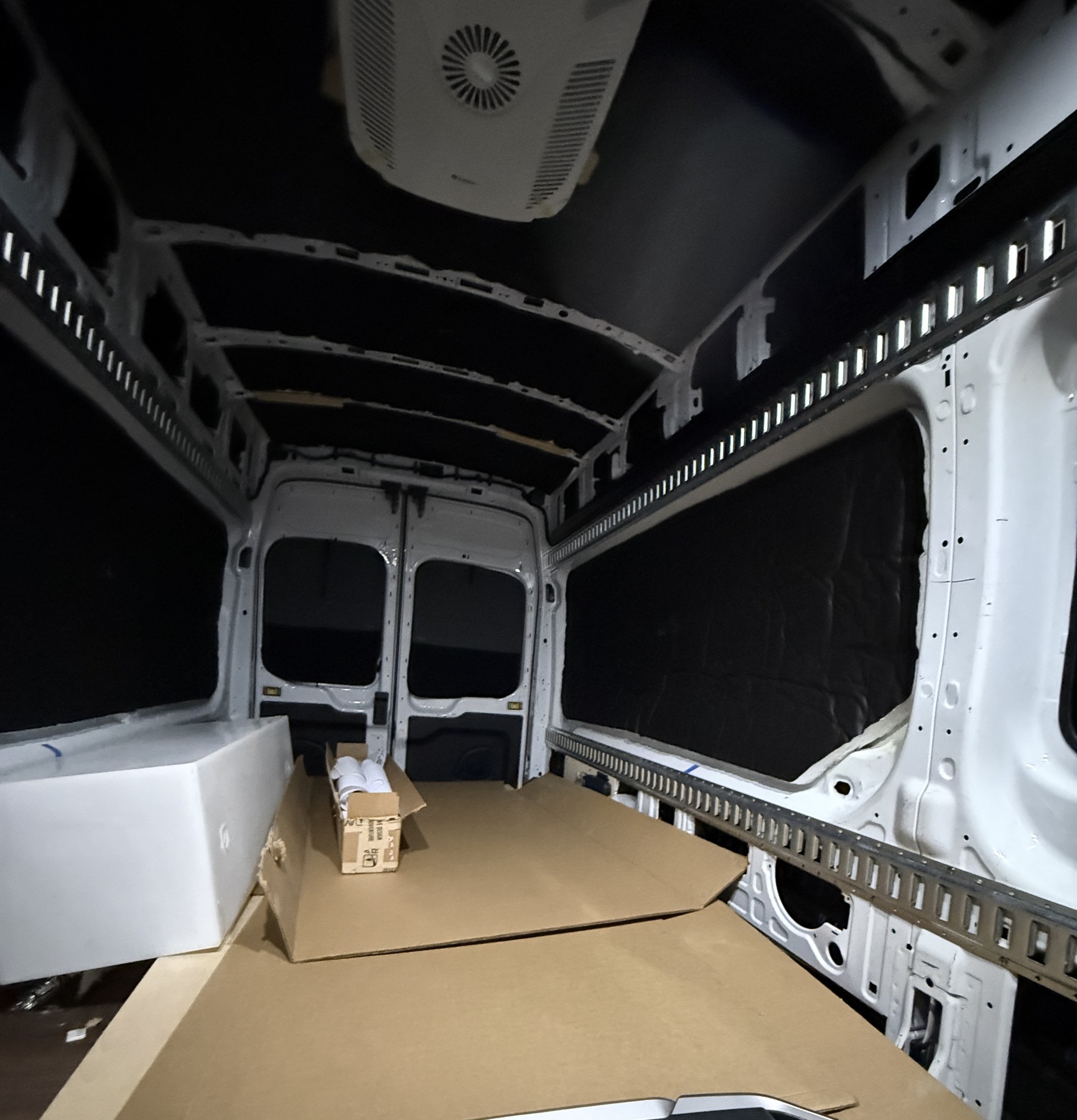
Climate controlEcoCool air conditioner, Espar heater2 stories
PowerSolar, EcoFlow setup, shore power3 stories
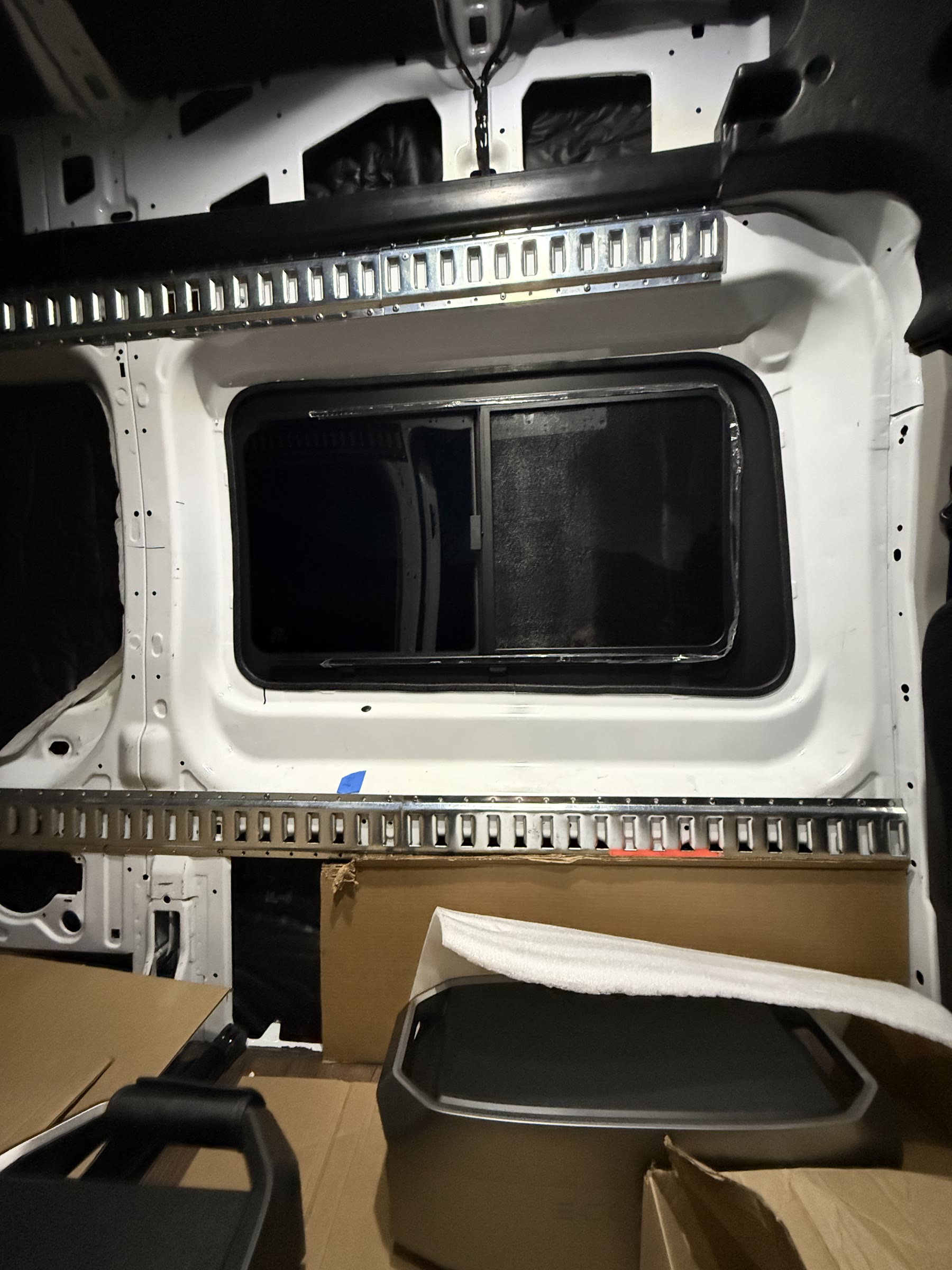
Roof & exteriorDriver-side slider window1 story
Cabinet structureOverhead cabinet supports1 story
The sleeping planEast-west bed, garage underneath1 story
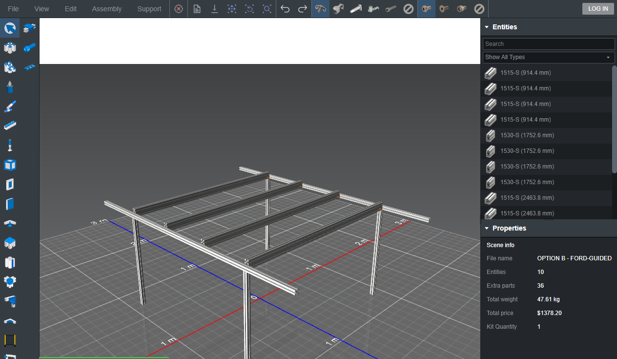
Don't just look at the plans.
Drag to rotate the bed frame. Hover over a member to identify it, or select it to see its size and product page. Change the height to explore the geometry.
Open the interactive bed model
Interactive design study
Explore the bed frame
What-if geometry, not an approved design. Lengths provisional. A is the preferred review direction, not approval. Wall anchorages are unknown; short supports stop above the floor, so the walls carry gravity load.
Drag to rotate. Hover, tap or keyboard-select J labels for frame joints; W labels for missing wall-interface designs. Labels are selection aids, not extra hardware. Escape closes the preview.
Dashed W zones: four full support faces + four rail ends in saved A. Eight zones do NOT mean eight bolts or that all physical holes have been located. No wall fasteners are modeled.
Context is schematic, not measured van fit. Assembled hardware is not enlarged on the frame. Simplified shapes are not manufacturer CAD or drill locations. The inspector provides an enlarged assembled or exploded close-up.
Van context and connection inspection
Why not approve A yet? The saved A has two short vertical supports per side, not a validated minimum. Adding a third or fourth per side does not by itself establish capacity. Wall fixing design, load distribution, body metal and reinforcement need qualified review.
FarOutRide reference (new tab) uses four main vertical supports TOTAL (two per side), plus four direct north-south rail-to-body brackets (two ends per side) and separate short rear-deck supports. That is not proof that our two-per-side design is sufficient.
The reference's "BEMM compliance" section acknowledges that its design may not follow Ford's self-supporting / floor-supported recommendation. It is a firsthand example, not Ford approval or validation for our bed. Its listed rivetnut count belongs to that build, not ours.
Our W01-W04 mark full short-support interface zones; W05-W08 mark rail-end reference zones. FarOutRide uses external corner brackets with extrusion-slot T-nuts/profile bolts and separate body bolts into rivetnuts. The saved support-to-rail 4302 brackets do not model those body fixings.
Ford 2022 FNA BEMM section 5.3.1 describes upper fixing locations as nonstructural with a 30 kg maximum and prohibits relying on lining for support. This is not a bed capacity or a per-fastener allowance. Our strips end above the floor; wall gravity load is unresolved, not merely anti-rattle restraint.
Hardware compatibility and floor anchors remain unresolved. No physical verification is implied. Ford's upper wall fixing points must not be assumed to carry the primary bed load.
Schematic cargo skeleton, not Ford body CAD. Length and maximum height use Ford's nominal 2022 unconverted-van specifications. The 70.2 in width is only a legacy Ford 2015 reference, not verified for this 2022 van. Rib spacing, roof shape and the bed's alignment to the rear are illustrative. Finished floor, lining, wheel housings, GoCode pockets and actual fixing points are not modeled. Do not infer fit or drill locations.
The saved frame is about 72 in wide, wider than the provisional 70.2 in reference. This mismatch needs measured wall/pocket geometry; the reference skeleton does not establish a collision or a fit.
Each crossmember end joins a north-south rail through a saved candidate internal anchor assembly. The vertical supports use separate external corner brackets. These are distinct joints, not one connector serving both directions. The middle crossmembers use the same internal anchor concept as the outer ones, not floating external cams. A bracket-only alternative would be a different connection design, not an automatic substitution.
J labels remain visible to make concealed connections inspectable. They are not physical parts. Removing a member removes its related joint groups. Slot alignment, machining and fastening still require review.
Manufacturer-suggested 3320 T-nut/bolt reference (new tab). Saved 3526 kits are not silently replaced. Compatibility and bolt engagement remain unresolved.
Sources for the provisional van envelope:
- Ford 2022 Police & Special Service Vehicles, Transit PTV specs, printed pp. 40-41 (PDF page 22) (new tab)
Ford-authored primary document on a dealer mirror. Extended 148 high-roof T-250 SRW: cargo floor length 172.2 in; maximum cargo height 81.5 in. Not rib coordinates or a finished interior survey.
- Ford 2015 Transit preliminary technical specifications - legacy width reference only (new tab)
Primary Ford historical reference: 70.2 in maximum load width excluding wheelhouses. Different model year; provisional visual guide only, not a 2022 width finding or width at this bed height.
Experiment with parts
The saved 1530-S crossmembers are tall, with 3 in vertical. Try 3 in horizontal north-south without changing the original model. This trades section orientation, not an automatic fix. Crossmember undersides stay at the chosen clearance.
1530-S manufacturer section properties (new tab): Ix 1.8127 in^4 / Iy 0.4957 in^4. These are section properties, not this frame's capacity. Loading, span, joints and support conditions still require qualified review.
10 active / 0 removed. Each option keeps its own edits until reset; changes remain local to this page.
Try a different height
Local exploration only. Wall strips and the top frame move together; wall attachment remains hypothetical. Nothing is saved to the design files.
30-42 in, in 0.5 in steps. Reset restores the exact saved 36 in reference geometry.
- Central clearance
- 36 in
- Highest crossmember top
- 39 in
- Frame top / rails included
- 39 in
- Nominal deck top (+0.75 in)
- 39.75 in
- Change from 36 in reference
- 0 in
Prepare context for your own AI assistant
This is not a live chatbot. Review this plain-text brief before copying. It follows the current option, valid height and selected part. Copying sends no outbound request.
Review the current brief, then copy or select its text.
Model created with an AI-assisted workflow; this viewer uses deterministic local geometry. Simplified solid profile envelopes, not slot detail. Connection symbols indicate candidate joint groups, not hardware CAD. Deck height is a nominal calculation, not a drawn or verified installation. No structural, feasibility or cost conclusion is provided.
The person behind the project
I'm Julia Lieberman.
This is my Transit conversion, and I am learning the hands-on work as I go.
I am not doing every part alone. Dan Moore in Salt Lake City completed the air conditioning, heater, insulation, solar, shore power, and window installations. The headliner shelf was my first finished hands-on project.
This journal brings together that work, my own projects, and the AI-assisted planning behind the next decisions.